In my prior post about harmonics I delved into the sine wave. In this post I want to show a practical use of this understanding.
I have produced a spreadsheet here, it's actually an old example I used for staff training but it nicely demonstrates the principle. Cell B1 contains the amplitude of the detected waveform, you can change this to see the impact on the detected signal in cell H1. To the signal in column B are added three noise sinusoids in columns C, D, and E. In column F is the reference sine wave which is used to detect the signal sine wave. Then column G contains the summation of the sine waves, and in column H I simply multiply the sum of the sine waves with the reference sine wave.
So this is creating the following sine waves.
Where the three noise components are shown and the tiny signal (red) is also shown.
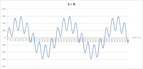
Add these together and you get the following waveform.
This is what would appear on the time-domain trace of an oscilloscope and it is evident that, using conventional measurement, the signal does not even appear as a visible feature in the result.
However as the spreadsheet shows, by multiplying the signal above by a sine at the same frequency one can change the signal amplitude (B1) and the correct amplitude of the signal is extracted from the above (H1). In my
previous post I showed a spectrum plot (final graphic) that was produced by Picoscope from a real signal (multiplication of two sines). To get the spectrum a succession of sine waves are multiplied with the signal plus noise, real world signal. In the case here we are essentially doing the same thing but using one sine wave of a fixed frequency, the higher frequency of this calculation are then removed using an average (which is a sort of low pass filter) to give the amplitude of the signal.
So I am now close to a position where I can address the question that is bugging me. Were one to flash a light for half a second every one second, there would be odd harmonics in the current demanded by the light at 3Hz, 5Hz, 7Hz etc. They are real as they can be detected using a conventional RMS voltmeter and filter. But what causes these harmonics?
And no, saying it is the result of the Fourier Transform, as most of the internet does, is not an answer. That is circular reasoning based on trigonometry, which is not enough because we know these harmonics are a real physical thing.


No comments:
Post a Comment